 Control
In this menu all the parameters related to the control of the platform can be found. There are 3 panels, each one showing a different menu of configuration.
Phases
In this panel, the flight phases that will control the aircraft at different stages of the operation are created (defined not configured).
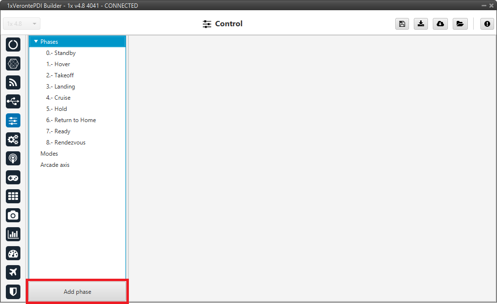
Phases panel
To create a new phase click on Add phase, the user can then select a phase already created or create a new one.
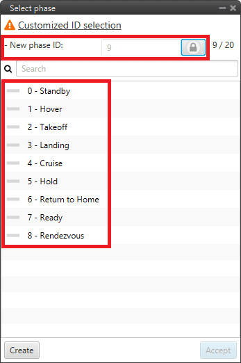
Phases panel - Create phase
To add a phase already created, select the desired phase and click Accept.
By default, when a new phase is created, it is assigned with the consecutive ID.
However, if the user wants to create a new phase with a specific ID, the New phase ID option can be “unlocked” by holding down
 until the process is fully completed (during the unlocking process this icon
  is “painted”).
Once unlocked (when it appears as
 ), the user can assign the desired ID to the new phase.
Finally, click Create and the new phase will be added to the list of phases.
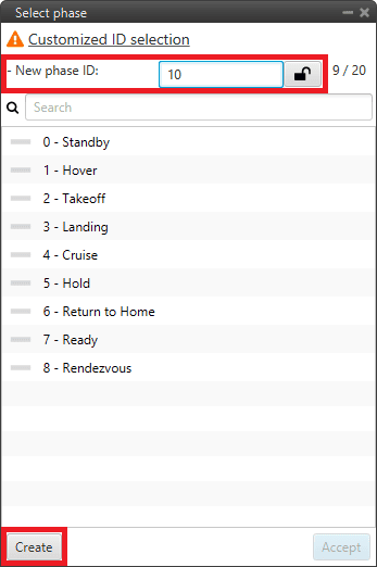
Phases panel - New phase ID
In addition, by right clicking on the phase, the user can rename, copy or remove it:
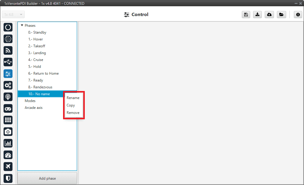
Phases panel - Phase options
Note
The configuration of the phases (guidance and control commands) is done in the Block Programs menu.
Modes
Modes
This tab allows the creation of custom flight modes. The flight modes determine who is in charge of controlling each one of the aircraft control channels.
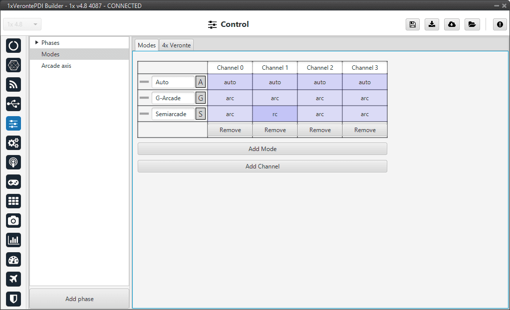
Modes tab
There are 4 different control modes and it is possible to combine them to create custom flight modes. The options available are:
auto: Automatic mode. The control channel is controlled totally by the autopilot.
rc: Radio Control mode. The control is totally carried out manually. The movements on the pilot stick imply directly movements on the servo linked to that control channel.
arc: Arcade mode. The autopilot aids the radio controller during the flight, i.e it could be considered as a mix between automatic and manual. The movements on the pilot stick are the input values on the control system, so the pilot commands a desired pitch, roll, IAS, heading and so on, and is the control system who is in charge of making the platform follow those commands.
mix: In this mode, it is possible to select in which step of the controller will enter the pilot command.
Example
For example, the pitching of an aircraft is commonly controlled with 3 PID being: flight path angle, pitch and pitch rate. In the arcade mode the pilot command will be a desired flight path angle that enters as input of the whole control system, but in the Mix mode is possible to select where we want the command to enter, so the pilot command could be pitch (entering in the second PID directly) or pitch rate (entering directly on the third PID).
The control system will take this input as a disturbance that it wants to discard because the final objective is to match the input of the first PID (a desired flight path angle in this case), so the Mix mode can be used to make small corrections when the aircraft is following a route for example, where we want it to move slightly towards a certain direction by introducing a value directly on the roll PID.
To change any of this options, click on the cell the user would like to change and the next option will be set.
Warning
The name of the mode does not have to correspond to the configuration of the mode.
For example, the user can name the mode as Auto but set the channels as rc (manual):
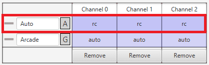
Modes configuration
Moreover, although the mode is set “sensefully” here, in the block configuration (Block Programs menu) the control does not have to correspond to this.
For example, if a channel is configured as manual (rc) here but then the control is configured so that the stick input does not control the channel, it will be auto control even though manual is specified. See the following example, where for consistency, the blocks in the ‘True’ and ‘False’ cases should be inverted:
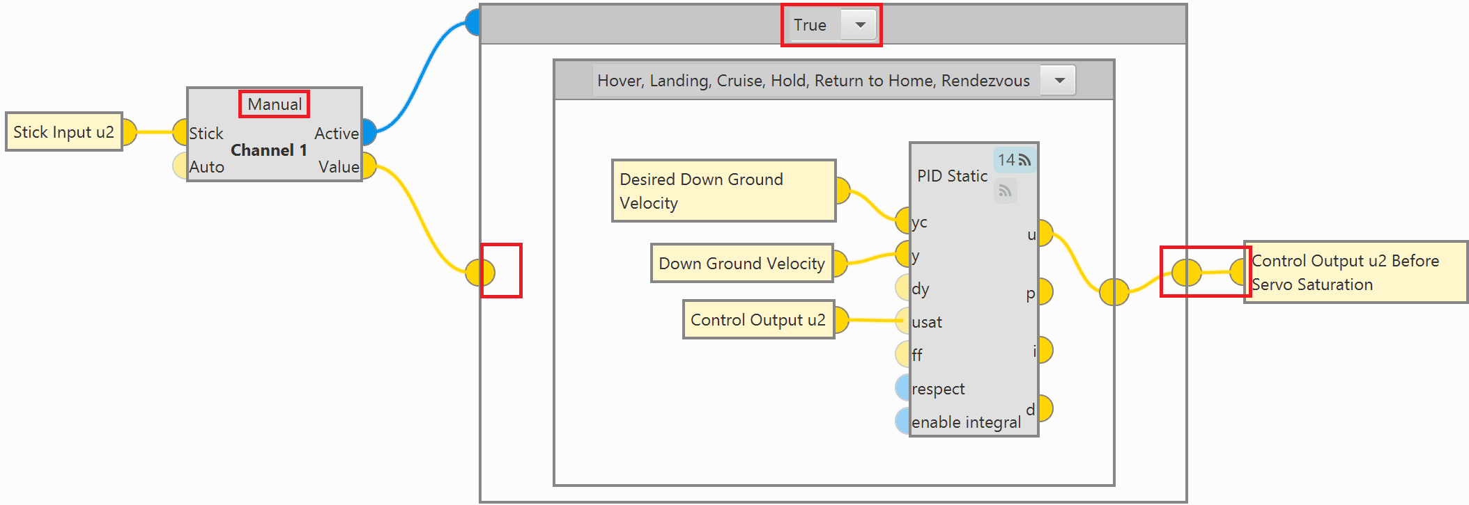
Modes configuration in blocks
So, it is the user’s responsibility to build the configuration correctly. In case of having any questions, the user should contact the support team (create a ticket in the customer’s Joint Collaboration Framework; for more information, see Tickets section of the JCF manual).
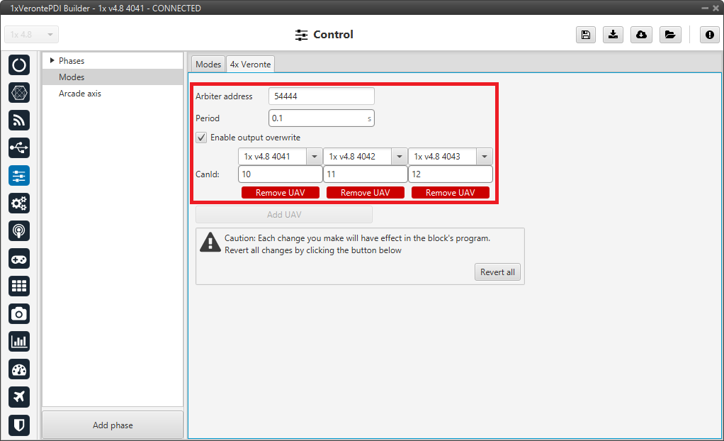
4x Veronte
This tab allows the user to configure an Autopilot 1x to operate in an Autopilot 4x.
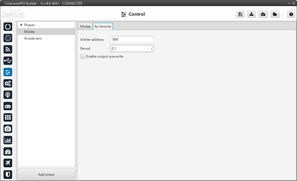
4x Veronte tab
Arbiter address: By adding the arbiter address, Veronte Ops will recognise it as part of a 4x unit group, and it will also be possible to do HIL simulations (with Veronte HIL Simulator) with this 4x group.
Note
If the arbiter address is set to 999, there is no arbiter.
Period: Sending period of CAN 4x messages. For more information on the transmission of CAN 4x messages, refer to the CAN Setup - Input/Output section of this manual.
Enable output overwrite checkbox: Allows the output to be overwritten when checked.
By enabling it, a table can be created in which columns correspond to each Autopilot 1x and the CanID row to the ID of the CAN message through which each Autopilot 1x communicates information with the other Autopilots 1x within the Veronte Autopilot 4x. Each CAN Id is associated to the CAN 4x producer/consumer of the AP in which it is configured. For more information on CAN 4x, refer to the CAN Setup - Input/Output section of this manual.
Important
This option must work in conjunction with the AP Selection block.
An example of configuration is presented below:
4x Veronte panel - Example of use
So in this example, Autopilot 1x with address 4041 will share information with Autopilots 1x with addresses 4042 and 4043 via CAN messages with ID 10.
Arcade axis
Arcade axis panel enables the option of changing the center of the system axes. This option is used to create axis systems referred to a certain point or direction, for example, it is useful when the pilot wants all movements to be made with respect to them (Ground axes). In this way, if the pilot commands a right turn, the aircraft will turn to the right relative to the pilot, rather than the right relative to the aircraft (Body axes).
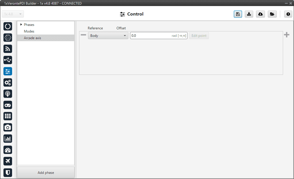
Arcade axis panel
It is possible to add up to 5 axes systems, being able to choose between the following types:
Body: Fix the axes in the UAV. It is standard for the pilot.
Ground: Fix the axes in the 1x GND unit.
Point: Fix the axes in a point that user defines.
Heading: Fix the axes in the the heading defined.
Desired heading: Fix the axes in the desired heading.
Tangent direction: Fix the axes in the tangent direction of the designed path.
Desired yaw: Fix the axes in the desired yaw.
An automation can be used to select an Arcade Axis in flight. For more information, check the Actions - Automations section of this manual.